| Home Synthesizers StudioFactory SynFactory SoftSynt Analog About rebuild design Modules Docs 1 to 3 4 to 6 7 to 9 Datasheets Tools DIY Info FPGAs Games Software Hardware Pinball Tech | |||
ResetCH()
Synthesizer Techniques
| ||||||||
 |
 |
 |
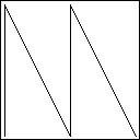
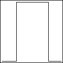
| Saw wave | Triangle wave | Pulse wave |
The generation of the 'waveshapes' is done with a three step process within the oscillator.
[IMG] 1 v/oct exp. -> integrator -> waveshaperThe 1v/oct control voltage is converted to a linear voltage or current. An intergrator with reset comparator creates the saw-wave. This saw-wave is used by the waveshaper to generate the other available waveshapes.
The triangle is created by flipping the saw over the x-axe on the right moment. The block or pulse shape is the output of a comparator with one input at the sawwave and the other input at a offset voltage. By changing the offset voltage the pulselength can be changed (PW). This also changes the harmonics generated by the oscillator. Varing the offset slowly a nice phasing effect results. This effect is called Pulse Width Modulation (PWM).
A sinus-wave can be generated by 'rounding' the edges of a triangle-shape smooth. For more harmonic rich contents some of the waveshapes can be combined with a mixer.
CH2('The filter (VCF)')The oscillator generates sounds with many harmonics. A filter can be used to make the sound more natural sounding. Classic mechanical instruments don't generate perfect saw or triangle shaped sounds. The casing and shape of the instrument changes the spectrum of the sound. Some frequencies are being softened while others are amplified. The filter in an analog synth can be used to imitate the working of an instrument body.
Most filters have two main parameters. These are the cutoff frequency and resonance. The cutoff-frequency defines a point in the spectrum. All frequencies higher as the cutoff-frequency will soften with increase in frequency. All frequencies lower as the cutoff will be passed with no change. This is only theorectical because no filter is perfect, so a small amount of the lower frequencies will also be filtered.
The resonance setting can give frequencies around the cutoff point extra amplification. This can give extra 'sharpness' to the sound. Setting the resonance too high can cause the filter to self oscilate producing a sinuswave at the cutoff frequency. Most filters have a voltage controllable cutoff frequency, but few offer a control input for the resonance. The resonance can normally only be changed with a knob on the front panel. The type of filter descibed above is called a lowpass filter, because it let frequencies below the cutoff-frequency through. An highpass filter is just the inverse of the lowpass filter. All frequencies above the cutoff will pass through and below are filtered. Combining a lowpass with a highpass filter gives a bandpass filter. The bandpass filter only let frequencies close to the cutoff frequency through, all others are filtered. Increasing the resonance with a bandpass filter narrows the band which it let through.
Not every filter reduces frequencies wih the same strength. The amount of attenuation depends on two factors:
- The filter design
- The range of input frequencies
The attenuation strength of a filter is expressed in decibells per octave (dB/oct). Filters with higher numbers filter better. Every internal filter stage will add a 6 dB extra attunuation per octave. This is again only theoretical because not all filterstages have the same characteristics, due to component tolerance. So a 24 dB/oct filter has maybe a 20 dB/oct slope for some frequency range. Synthesizers can be found with 6, 12, 18 or even 24 dB/oct filters. The type of filter used depends largely on the sound you want to generate and ofcourse the type of filter(s) available on your synth.
CH2('Voltage Controlled Amplifier')The Voltage Controlled Amplifier or VCA is an amplifier with controllable gain (or amplification). There are two types of VCAs. One with linear voltage response, the other with logarithmic responce. Both methods have there specific uses, so both types of VCAs should be present in the synthesiser. In the best case each VCA has both modes of operation. Either providing two seperate inputs or having a switch to change the responce curve.
CH2('Experimenting')We have now the core of synthesis. Generating a tone (VCO) changing it timbre (VCF) and amplify the sound (VCA). I recommand building this basic patch on your synthesizer and experiment with different VCO and VCF settings.
CH1('Extending the basic patch') CH2('Limitations of the basic patch') Although all the basic elements of a sound are available in the basic patch, it is not musically very interesting. The sound plays continuesly and all you get is a single tone. That's why we will expand the basic patch in this chapter with more modules and interconnections. CH2('Adding dynamics with an ADSR')The bigest problem with the basic patch is that the sound is constant playing. We will add dynamics to the sound by using a contour or envelope generator. The normaly used abbriviation for the envelope generator is ADSR. This is derived from the 4 main paramers Attack, Decay, Sustain and Release. Connect the output from a ADSR module to the exponational gain control of the VCA. Set the gain-offset to zero. No sound will be audiable. Start with all 4 parameter knobs of the ADSR to the middle position and press the manual trigger or gate. Experiment with different settings for the ADSR knobs. The sound is now already much more musical.
Extra dynamics can be obtained by connecting a second ADSR to the cutoff-modulation input of the filter. Best result is archived when both ADSR controllers can be simultainious triggered. The total envelope time of the ADSR connected to the VCF should be smaler as the time of the ADSR connected to the VCA, otherwise only a part of the timbre change is actualy audiable.
CH2('Adding LFO modulation')A Low Fequency Oscillator (LFO) is basically the same module as a VCO, except it oscilates at a much lower frequency. Because of the lower frequency range, the LFO can not be used as an audio source. The LFO is used similair to the ADSR. It can automatic change parameters of other modules. The ADSR only runs a single time after a trigger pulse, the LFO continuesly cycles through its waveform. Simple LFO modules usualy don't have any control inputs.
A nice effect can be archived by connecting the triangle or sine output of an LFO to the cutoff-control input of the VCF. Now the timbre of the sound slowly changes over time. [IMG schematic/output] [MP3?]
CH2('Keyboard control')Most keyboards for analog equipment are monophonic. This means that only one key can be played at the same time. The most common way to build a monophonic keyboard is by means of a resistor ladder. By pressing a key, part of the resistor ladder is rerouted to earth, so the output voltage changes. The voltage drop is linear 1 volt every 12 keys (1 v/oct).
Analog keyboards can be low-key significant, which means the lowest key pressed is used (monophonic so only one key can be detected). Or they can be high-key significant, which means the highest key pressed is played. Afcourse there can be other not allocations Like last key pressed is used, but this requires additional electronics. After the resistor ladder a sample and hold converter is placed to hold the last pressed key, even when it is released. This is nessesary for notes with long decay or release times. These sounds will continue to play, even when the note is released.
There is second signal on a keyboard, this is the gate signal. This signal is high when a key is pressed. It is used to start and control the envelope generators.
 CH2('The oscillator (VCO)')